![]()
The Amazing Stress Camera: An Interactive Discovery Experience
Timothy
A. Philpot, University of Missouri - Rolla
Richard H. Hall, University of Missouri
- Rolla
Abstract
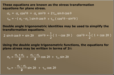
Stress transformation
is one of the most important foundational concepts in engineering design.
However, the nature of stress transformation is hard for students to understand
since it is an abstract, mathematical concept that is not easily visualized.
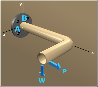
The Amazing Stress Camera is an interactive software animation that helps
students discover the meaning of stress transformation through an analogy
with a familiar everyday object: a simple camera.
1. Introduction
The Mechanics of Materials
course is one of the core courses for students in civil, mechanical, aerospace,
metallurgical, ceramic, geotechnical, and architectural engineering programs.
The course is also included in architecture, engineering mechanics, engineering
physics, engineering management, and engineering technology curricula.
The Mechanics of Materials course introduces students to the principles
involved in designing typical components found in machines and structures
such as drive shafts, floor beams, pressure tanks, and bolted connections.
The course explores various common structural components, teaching students
how to analyze the effects of forces and loads on the internal stresses
and deformations in the components.
![]()